WP2: Next Generation of Rubust Offshore Blades
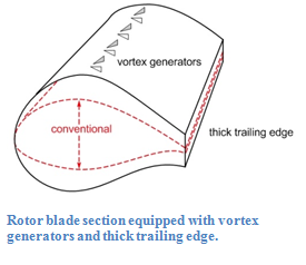
Background: The quest for robust and higher power output at reduced costs per offshore wind turbine drives the design towards increasingly larger rotor diameters that have positive influence on the usage of the electrical grid (by larger capacity factor) and wind farm power production. To counter the increased mechanical loading in extreme off-design conditions these increasingly larger rotors have relatively small solidity. The much slender rotors therefore have to be equipped with thicker rotor blades. The drawback of thicker blade sections is that the use of these rotors are accompanied with relative large uncertainties in performance. This is motivating the application of vortex generators (VG) and thick trailing edges. This technique is also not without risk; the modelling of rotors with vortex generators and thick trailing edges is a challenge in itself . The entire sector would be greatly assisted when reliable models for the use of vortex generators and thick trailing edges would be available.
In this work package Siemens is collaborating with ECN and TU Delft in the theoretical model development and practical implementation of these flow device models to the RFOIL blade section design code. Siemens will perform extensive wind tunnel measurements together with the TU Delft PhD student and bring in the project the results of previous wind tunnel experiments. The knowledge and experience of the Siemens CFD modelling group will be put to use in this work package.
Objective: The overall objective of work package ‘Robust Power Performance’ is to generate the knowledge and design capability that enables the development of the next generation of larger and lighter offshore wind turbine blades that do not rely on failure prone features and thereby lower the cost of energy. More specifically this work package is to enable the accurate and reliable simulation of the effects of vortex generators and thick trailing edges on wind turbine performance by extending the existing airfoil design tool RFOIL with models for the effect of vortex generators and thick trailing edges on airfoil aerodynamic performance that are validated against experimental data. From numerical and wind tunnel experiments flow field data will be obtained and analyzed to create a vortex generator model that will be implemented in RFOIL. Partners in this work package ECN, Siemens, and TU Delft make sure that a practical solution for industry is developed that is grounded in solid scientific research.
The work is organised along the following tasks:
Task 2.1: Increasing blade robustness: vortex generators
A literature survey of the state-of-the-art in vortex generator modelling will be performed and candidates for incorporation in an Integral Boundary Layer method as in RFOIL will be developed. Currently available numerical and experimental data will be collected that can be used to develop the new VG model. A practical range of VG configurations is determined and the mathematical and numerical formulation of the selected approach will be worked out and implemented in the current RFOIL code. Experimental data for airfoils with and without VG's from Task 2.4 is used to validate the implemented models.
Task 2.2: Increasing blade robustness: thick trailing edges
A literature survey will be performed on thick trailing edge drag models. Experimental and numerical data will be collected and used to create a better thick-TE drag model. This new model will be implemented in the current RFOIL code. For extremely thick trailing edges possible numerical (convergence) issues in RFOIL will be solved. Experimental data for airfoils with different trailing edge thicknesses from public domain and possibly from Task 2.4 is used to validate the implemented base drag model.
Task 2.3: High-fidelity CFD parameter sweeps
Define a matrix of numerical experiments that cover the required range of vortex generator and trailing edge thickness parameters; e.g. co-rotating and/or counter-rotating VG's, VG spanwise densities, VG height variations, VG streamwise alignments, Reynolds numbers, flow conditions, airfoil types, trailing edge heights. For this matrix of condition high-fidelity CFD simulations will be performed and the full flow solution data near the airfoil will be stored. From this data reduced quantities like lift, drag, and pitching moment will be derived and the spanwise averaged development of integral boundary layer quantities like displacement thickness, momentum thickness, energy thickness, skin friction, etc. will be determined. The results will be used in Task 2.1 and Task 2.5 for model development and/or validation.
Task 2.4: Advanced blade section wind tunnel experiments
Airfoil geometries will be selected that will be measured in the wind tunnel with and without vortex generators and possibly with different trailing edge thicknesses and wind tunnel models for these geometries will be manufactured. A matrix of airfoil-VG configurations, flow conditions, and required measurement data will be determined and a time schedule for the wind tunnel measurements will be allocated. The wind tunnel tests will be performed accordingly and the experimental data will be post-processed and analysed for further use. These results will be used in Task 2.1 and Task 2.2 to validate the models implemented and possibly to enhance the model parameters afterwards.
Task 2.5: Vortex generator model development: CFD and wind tunnel experiments
PhD fundamental research on vortex generator physics and model development. The research aims at experimentally and numerically investigate the 3D flow of boundary layers with vortex generators, in order to develop both a model validation benchmark and a reduced order closure relation that can be used in integral boundary layer models and can be implemented in models such as RFOIL. The experimental results are developed at TUDelft boundary layer wind tunnel and the Low Turbulence wind tunnel, for both the cases of prescribed boundary layer flows with VGs and measurements on reference airfoils with VGs, including during stall and unsteady flow conditions (response to gust). The experimental methods involve high resolution Stereo PIV and Tomography, in order to capture the 3D vortical structures of the boundary layer and flow (both the average vertical structures and turbulence). The numerical flow field data from Task 2.3 is used and extended with CFD simulations for a range of parameters to create a vortex generator model for Integral Boundary Layer methods. From the numerical and experimental data reduced quantities like lift, drag, and pitching moment will be derived and the spanwise averaged development of boundary layer quantities like displacement thickness, momentum thickness, energy thickness, skin friction, Reynolds stresses and slip velocity, etc. will be determined. The range of configurations covered in the numerical simulations are used to develop a vortex generator model and the experimental data is used to calibrate the model parameters. The resulting new vortex generator model is implemented in Task 2.1. This research complements future efforts planned in the FP7 Avatar research project, of which ECN and TUDelft are also partners.
Task 2.6: Information and task coordination
Workshops, project meetings and conference calls will be held to make sure that the work package is on the right track and tasks between partners are well coordinated. Especially at the start of the project a kick-off meeting with all partners is required.
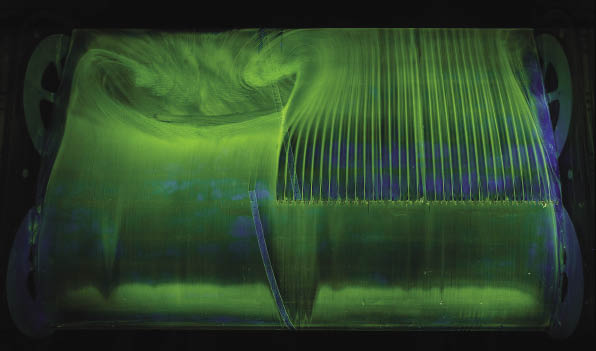
From www.windpowerengineering.com, June 1st 2013. Test performed by LM on VGs.
Return to Work Packages